
Skip to content

Below-the-hook

Lifting clamps

Crosby IP plate, beam and pipe clamps — individually proof tested to twice their working load limit and serialized, so the certificate matches the clamp in your hand.

Horizontal clamps

Rated per pair, not per clamp

A horizontal clamp marked 12 t is 12 t for two clamps working together. One on its own is not a 12 t clamp. Every horizontal model on this page says “per pair” on the rating for exactly this reason.

There is a minimum too

Too light is also wrong

Plate clamps need roughly 10% of the working load limit on them for the cam to bite properly. A big clamp on a light plate is not the safe choice it looks like.

Material matters

Hardness limits are real

Standard clamps grip material up to 363 HV10 (345 HB). Above that the teeth won’t bite — you need an H model to 472 HV10, or an S model for stainless.

2 series

Universal clamps

Lifts vertically, turns, and transfers horizontally

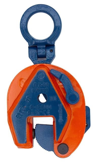
IPU10 Universal Lifting Clamp

IPU10 Universal Lifting Clamp

Lifts in any direction, with a full 180° turning range

0.5 – 30.0 t

per clamp

Universal - for lifting in any direction.

The clamp that does the most jobs. It lifts vertically, turns a plate through 180°, and transfers horizontally — so one clamp covers work that would otherwise need two types. Lock-open and lock-closed with a latch lets you pretension onto the plate and release it deliberately.

Jaw / grip range
0 – 6.13 in
Surface hardness
363 HV10 (345 HB) standard; 472 HV10 (450 HB) on the IPU10H
Minimum load
10% of the Working Load Limit (5% on the 0.5 t IPU10, and on material to 279 HV10)

Best for

  • Vertical lifting, turning, and transfer with one clamp
  • Plate shops handling a mix of orientations
  • Work where the plate has to be flipped, not just lifted
  • IPU10 — Standard, to 363 HV10 (345 HB) surface hardness
  • IPU10J — Larger jaw opening
  • IPU10S — For stainless steel material
  • IPU10H — For material to 472 HV10 (450 HB)
Crosby’s product details
  • Available in a wide variety of capacities and jaw openings.
  • Higher Working Load Limits available upon request.
  • Welded alloy steel body for strength and smaller size. Forged alloy components, where required.
  • Individually Proof Tested to 2 times the Working Load Limit with certification.
  • Crosby IP logo, Working Load Limit and jaw opening permanently stamped on body.
  • Each product is individually serialized, with the serial number and Proof Load test date stamped on body. User manual with test certificate is included with each clamp.
  • Available in a variety of styles: IPU10 - Standard clamp for materials with a surface hardness to 363HV10 (345 HB).
  • IPU10J - Larger jaw opening.
  • IPU10S - For use with stainless steel material.
  • IPU10H - For use with materials with a surface hardness to 472HV10 (450 HB).
  • Full 180° turning range for material transfer, turning or moving.
  • Lock open, lock closed ability with latch for pretension on material and then release of material.
  • Maintenance and repair kits are available.
  • Minimum WLL is 5% of maximum WLL for .5t IPU10 only.
  • Minimum WLL is 10% of maximum WLL for all other IPU10, IPU10J, IPU10S, IPU10H clamps.
  • For use with materials with a surface hardness to 279HV10, only 5% of minimum WLL is needed.
  • Temperature range -40 °F (-40 °C) to +212 °F (+100 °C)
35 models — sizes, jaw openings and stock numbers
ModelWLL (t, each)Jaw / grip range (in)Weight each (lb)Stock no.
IPU100.50 - 0.634.192701675
IPU1010 - 0.755.292701663
IPU1020 - 1.3818.32701677
IPU1030 - 1.5632.62701665
IPU104.50 - 1.5635.32701667
IPU1060 - 2.0052.92701669
IPU1090 - 2.0068.22701671
IPU10120 - 2.131262701679
IPU10160.2 - 2.501742701683
IPU1022.50.2 - 3.132782701687
IPU10300.2 - 3.133112701691
IPU10J0.50.63 - 1.194.192701647
IPU10J10.75 - 1.565.512702463
IPU10J31.56 - 3.1338.12702465
IPU10J4.51.56 - 3.1341.92702467
IPU10J62.00 - 4.0058.42702469
IPU10J92.00 - 4.0075.52701673
IPU10J122.13 - 4.251432701681
IPU10J162.50 - 5.001872701685
IPU10J22.53.13 - 6.133282701689
IPU10J303.13 - 6.133662701693
IPU10S0.50 - 0.634.192702275
IPU10S10 - 0.755.292702263
IPU10S20 - 1 .3818.72702277
IPU10S30 - 1.5632.62702265
IPU10S4.50 - 1.5635.32702267
IPU10S60 - 2.0052.92702269
IPU10S90 - 2.00652702271
IPU10H0.50 - 0.634.192702175
IPU10H0.750 - 0.755.292702163
IPU10H10 - 1.3818.32702177
IPU10H20 - 1.5632.62702165
IPU10H30 - 1.5635.32702167
IPU10H4.50 - 2.0052.92702169
IPU10H60 - 2.00652702171

Scrolls — all 35 sizes are listed.

  • *Design Factor based on EN 13155 and ASME B30.20.
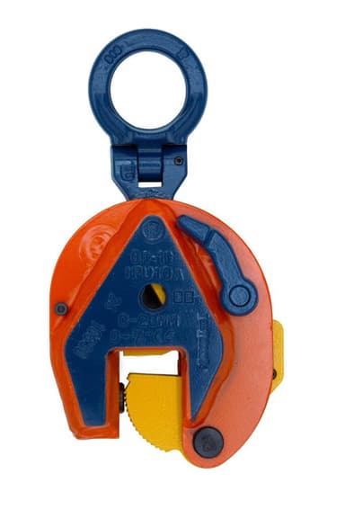
IPU10A Automatically Locking Clamp

IPU10A Automatically Locking Clamp

Locks on its own — no second trip up the stack

1.0 – 6.0 t

per clamp

For vertical transport of plates, with automatic closing feature.

An automatically locking version of the universal clamp. It engages without the operator setting the latch by hand, which matters when the clamp is going onto plate the operator can't easily reach.

Jaw / grip range
0 – 2 in
Surface hardness
363 HV10 (345 HB)
Minimum load
10% of the Working Load Limit

Best for

  • Plate stacks where reaching the clamp is awkward
  • Repetitive cycles where manual latching slows the job
  • Single-operator plate handling
Crosby’s product details
  • Available in a wide variety of capacities and jaw openings.
  • Higher Working Load Limits available upon request.
  • Welded alloy steel body for strength and smaller size. Forged alloy components where required.
  • Individually Proof Tested to 2 times the Working Load Limit with certification.
  • Crosby IP logo, Working Load Limit and jaw opening permanently stamped on body.
  • Each product is individually serialized, with the serial number and Proof Load test date stamped on body. User manual with test certificate is included with each clamp.
  • Full 180° turning range for material transfer, turning or moving.
  • Lock open, lock closed ability with latch for pretension on material and then release of material.
  • Minimum WLL of 10% of Maximum WLL.
  • For use with materials with a plate surface hardness to 279HV10, only 5% of minimum WLL is needed.
  • Maintenance and repair kits are available.
  • Temperature range -40 °F (-40 °C) to +212 °F (+100 °C)
3 models — sizes, jaw openings and stock numbers
ModelWLL (t, each)Jaw / grip range (in)Weight each (lb)Stock no.
IPU10A10 - 0.755.072701628
IPU10A20 - 1.3818.52701629
IPU10A60 - 2.00562701638
  • * Design Factor based on EN 13155 and ASME B30.20.
3 series

Vertical clamps

Straight vertical lifting from a rack or stack

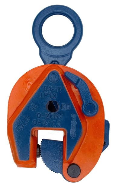
IP10 Vertical Lifting Clamp

IP10 Vertical Lifting Clamp

The basic vertical clamp, 0.5 through 30 ton

0.5 – 30.0 t

per clamp

For vertical lifting, turning and transfer.

Vertical lifting only — no turning range. If every lift is plate coming off a stack and going onto a table the right way up, this is the clamp, and it costs less than the universal.

Jaw / grip range
0 – 6.13 in
Surface hardness
363 HV10 (345 HB) standard; 472 HV10 (450 HB) on the IP10H
Minimum load
10% of the Working Load Limit

Best for

  • Straight vertical lifting from a rack or stack
  • High-volume plate handling in one orientation
  • Lower cost where the turning range isn't needed
  • IP10 — Standard, to 363 HV10 (345 HB) surface hardness
  • IP10J — Larger jaw opening
  • IP10S — For stainless steel material
  • IP10H — For material to 472 HV10 (450 HB)
Crosby’s product details
  • Available in a wide variety of capacities and jaw openings.
  • Higher Working Load Limits available upon request.
  • Welded alloy steel body for strength and smaller size. Forged alloy components, where required.
  • Individually Proof Tested to 2 times the Working Load Limit with certification.
  • Crosby IP logo, Working Load Limit and jaw opening permanently stamped on body.
  • Each product is individually serialized, with the serial number and Proof Load test date stamped on body. User manual and test certificate included with each clamp.
  • Available in a variety of styles: IP10 - Standard clamp for materials with a surface hardness to 363HV10 (345 HB).
  • IP10J - Larger jaw opening.
  • IP10S - For use with stainless steel material.
  • IP10H - For use with materials with a surface hardness to 472HV10 (450 HB).
  • Full 180° turning range for material transfer, turning or moving.
  • Lock open, lock closed ability with latch for pretension on material and then release of material.
  • Maintenance and repair kits are available.
  • Minimum WLL is 5% of maximum WLL for .5t IP10 only.
  • Minimum WLL is 10% of maximum WLL for all other IP10, IP10J, IP10S, IP10H clamps.
  • For plate surface hardness till 279HV10, only 5% of minimum WLL is needed.
  • Temperature range -40 °F (-40 °C) to +212 °F (+100 °C)
35 models — sizes, jaw openings and stock numbers
ModelWLL (t, each)Jaw / grip range (in)Weight each (lb)Stock no.
IP100.50 - 0.633.972701674
IP1010 - 0.754.852701662
IP1020 - 1.3816.82701676
IP1030 - 1.5630.42701664
IP104.50 - 1.5633.12701666
IP1060 - 2.0050.32701668
IP1090 - 2.0065.82701670
IP10120 - 2.131112701678
IP10160.25 - 2.501502701682
IP1022.50.25 - 3.132432701686
IP10300.25 - 3.132732701690
IP10J0.50.59 - 1.183.972701646
IP10J10.75 - 1.565.072702462
IP10J31.56 - 3.1336.42702458
IP10J4.51.56 - 3.1339.72702460
IP10J62.00 - 4.0055.82701705
IP10J92.00 - 4.0073.12701672
IP10J122.13 - 4.251282701680
IP10J162.50 - 5.001762701684
IP10J22.53.13 - 6.132872701688
IP10J303.13 - 6.133362701692
IP10S0.50 - 0.633.972702274
IP10S10 - 0.7516.82702262
IP10S20 - 1.3830.42702276
IP10S30 - 1.5633.12702264
IP10S4.50 - 1.5651.82702266
IP10S60 - 2.0060.62702268
IP10S90 - 2.0060.62702270
IP10H0.50 - 0.633.972702174
IP10H0.750 - 0.754.852702162
IP10H10 - 1.3816.82702176
IP10H20 - 1.5630.42702164
IP10H30 - 1.5633.12702166
IP10H4.50 - 2.0051.82702168
IP10H60 - 2.0060.62702170

Scrolls — all 35 sizes are listed.

  • *Design Factor based on EN 13155 and ASME B30.20.
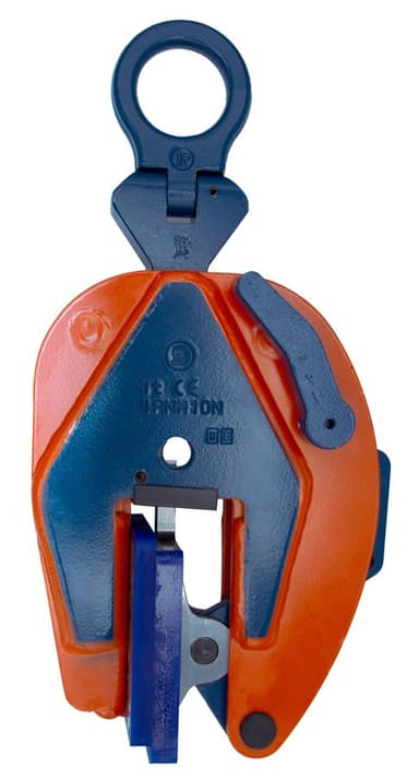
IPNM10 Non-Marring Lifting Clamp

IPNM10 Non-Marring Lifting Clamp

Grips without leaving tooth marks

0.5 – 2.0 t

per clamp

For use in almost all sectors of industry where, during the lift or transfer, no damage to the material is permitted.

A standard clamp's cam bites into the plate — which is fine on structural steel and unacceptable on a polished, painted, or stainless surface. The non-marring clamp grips without marking the finish.

Jaw / grip range
0 – 1.56 in
Surface hardness
Suits soft and finished surfaces — confirm the material with us
Minimum load
10% of the Working Load Limit

Best for

  • Polished, coated, or painted plate
  • Stainless and architectural finishes
  • Anything where the surface is the product
Crosby’s product details
  • Available in a wide variety of capacities and jaw openings.
  • Higher Working Load Limits available upon request.
  • Welded alloy steel body for strength and smaller size. Forged alloy components, where required.
  • Individually Proof Tested to 2 times the Working Load Limit with certification.
  • Crosby IP logo, Working Load Limit and jaw opening permanently stamped on body.
  • Each product is individually serialized, with the serial number and Proof Load test date stamped on body. User manual with test certificate is included with each clamp.
  • Full 180° turning range for material transfer, turning or moving.
  • Lock open, lock closed ability with latch for pretension on material and then release of material.
  • Material must be clean and dry.
  • There is no minimum WLL required.
  • Maintenance replacement kits are available.
  • Temperature range -4° F (-20° C) to 158° F (70° C)
  • Optional with brake pad lining for temperature range -40° F (-40° C ) to +392° F (+200° C)
  • Special jaw openings or curved jaws upon request.
7 models — sizes, jaw openings and stock numbers
ModelWLL (t, each)Jaw / grip range (in)Weight each (lb)Stock no.
IPNM10N0.50 - 0.385.952703811
IPNM10N10 - 0.759.72703738
IPNM1020 - 1.56322703442
IPNM10P0.50 - 0.386.172703278
IPNM10P10 - 0.759.922703279
IPNM10NJ10.81 - 1.4410.42703814
IPNM10NJ110 - 1.0012.12703819
  • *Design Factor based on EN 13155 and ASME B30.20.
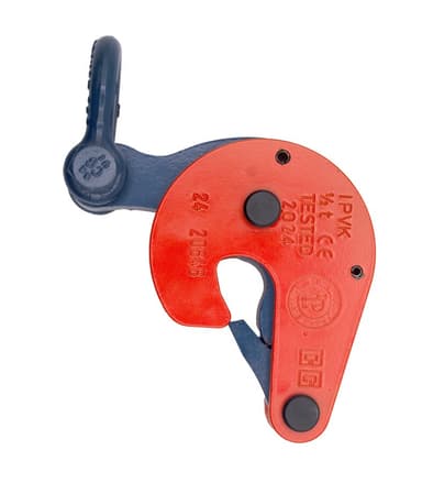
IPVK Vertical Lifting Clamp

IPVK Vertical Lifting Clamp

A compact 0.5 ton vertical clamp for thin plate

0.5 – 0.5 t

per clamp

The smallest vertical plate clamp in the range — half a ton, a jaw to 0.63 in, and under four pounds. For thin plate and sheet where a full-size clamp is more than the job needs.

Jaw / grip range
0 – 0.63 in

Best for

  • Thin plate and sheet
  • Light, frequent vertical picks
Crosby’s product details
  • Available in a wide variety of capacities and jaw openings.
  • Higher Working Load Limits available upon request.
  • Welded alloy steel body for strength and smaller size. Forged alloy components, where required.
  • Individually Proof Tested to 2 times the Working Load Limit with certification.
  • Crosby IP logo, Working Load Limit and jaw opening permanently stamped on body.
  • Each product is individually serialized, with the serial number and Proof Load test date stamped on body. User manual with test certificate is included with each clamp.
  • Maintenance and repair kits are available.
  • Manufactured by an ISO 9001 facility.
  • Temperature range -40 °F (-40 °C) to +212 °F (+100 °C)
1 models — sizes, jaw openings and stock numbers
ModelWLL (t, each)Jaw / grip range (in)Weight each (lb)Stock no.
IPVK0.50 - 0.633.532700116
  • *Design Factor based on EN 13155 and ASME B30.20.
5 series

Horizontal clamps

Carries plate flat — always used in pairs

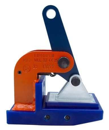
IPHNM10 Horizontal Non-Marring Clamp

IPHNM10 Horizontal Non-Marring Clamp

Horizontal transfer with pretension, without marking the plate

0.5 – 2.0 t

per pair

For Horizontal Lift and Transfer with Pretension System.

Horizontal clamps carry a plate flat, in pairs, and this one does it without marking the surface. The spring pretension keeps the clamp engaged before the load comes on.

Jaw / grip range
0 – 2.38 in
Surface hardness
Suits finished surfaces — confirm the material with us
Minimum load
10% of the Working Load Limit

Best for

  • Moving finished plate flat between stations
  • Coated or polished material handled horizontally
  • Loading tables and machining centres
  • IPHNM10 — Standard jaw
  • IPHNM10J — Larger jaw opening
Crosby’s product details
  • Available in a wide variety of capacities and jaw openings.
  • Higher Working Load Limits available upon request.
  • Welded alloy steel body for strength and smaller size. Forged alloy components, where required.
  • Individually Proof Tested to 2 times the Working Load Limit with certification.
  • Crosby IP logo, Working Load Limit and jaw opening permanently stamped on body.
  • Each product is individually serialized, with the serial number and Proof Load test date stamped on body. User manual with test certificate is included with each clamp.
  • Maintenance and repair kits are available.
  • IPHNM10: Temperature range -4 °F (-20 °C) to +158 °F (+70 °C)
  • IPH10/J: Temperature range -40 °F (-40 °C) to +212 °F (+100 °C)
4 models — sizes, jaw openings and stock numbers
ModelWLL (t, per pair)Jaw / grip range (in)Weight each (lb)Stock no.
IPHNM100.50 - 0.7542703287
IPHNM1010 - 1.3872703288
IPHNM1020 - 1.18162703290
IPHNM10J21.19 - 2.38172703291
  • *Design Factor based on EN 13155 and ASME B30.20.
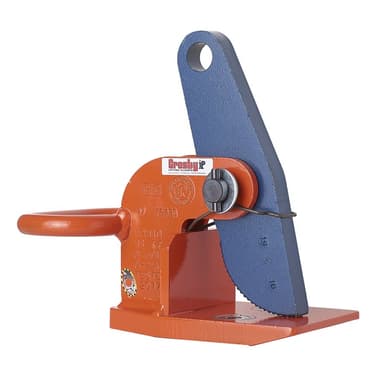
IPH10 Horizontal Lifting Clamp

IPH10 Horizontal Lifting Clamp

Magnets and pretension hold it on before the load comes up

0.5 – 12.0 t

per pair

+No handle or magnets.

For lifting and transferring plate flat. Built-in magnets and a spring pretension system hold the clamp against the plate while you rig, so it doesn't drop off before the sling takes up — the single most irritating thing about horizontal clamps.

Jaw / grip range
0 – 4.75 in
Surface hardness
363 HV10 (345 HB)
Minimum load
10% of the Working Load Limit

Best for

  • Transferring plate flat between stations
  • Plate that would sag on a single pick point
  • Rigging where the clamp must stay put before tension
  • IPH10 — Standard jaw
  • IPH10J — Larger jaw opening
Crosby’s product details
  • Available in a wide variety of capacities and jaw openings.
  • Higher Working Load Limits available upon request.
  • Welded alloy steel body for strength and smaller size. Forged alloy components, where required.
  • Individually Proof Tested to 2 times the Working Load Limit with certification.
  • Crosby IP logo, Working Load Limit and jaw opening permanently stamped on body.
  • Each product is individually serialized, with the serial number and Proof Load test date stamped on body. User manual with test certificate is included with each clamp.
  • Maintenance and repair kits are available.
13 models — sizes, jaw openings and stock numbers
ModelWLL (t, per pair)Jaw / grip range (in)Weight each (lb)Stock no.Note
IPH100.50 - 0.753.972703297Supplied without handle or magnets
IPH1010 - 1.385.52703298Supplied without handle or magnets
IPH1020 - 2.3812.12703522—
IPH1030 - 2.3816.62703523—
IPH104.50 - 2.3823.22703524—
IPH1060 - 2.3828.72703525—
IPH1090 - 2.3840.82703526—
IPH10120 - 2.3847.52703527—
IPH10J32.38 - 4.75192703533—
IPH10J4.52.38 - 4.75262703534—
IPH10J62.38 - 4.75332703535—
IPH10J92.38 - 4.75452703536—
IPH10J122.38 - 4.75532703537—
  • *Design Factor based on EN 13155 and ASME B30.20.
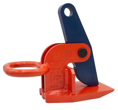
IPH10E Horizontal Lifting Clamp — Basic

IPH10E Horizontal Lifting Clamp — Basic

The horizontal clamp without the magnets

2.0 – 12.0 t

per pair

For horizontal lifting and transfer.

Same non-sagging horizontal design as the IPH10, without the magnets and handle. Lower cost where the rigger can hold the clamp in position while the sling takes up.

Jaw / grip range
0 – 2.38 in
Surface hardness
363 HV10 (345 HB)
Minimum load
10% of the Working Load Limit

Best for

  • Horizontal plate transfer on a budget
  • Two-rigger operations where holding the clamp isn't a problem
  • Lighter duty horizontal work
Crosby’s product details
  • Available in capacities of 2.0 thru 25 metric tons.
  • Higher Working Load Limits available upon request.
  • Welded alloy steel body for strength and smaller size. Forged alloy, components where required.
  • Equipped with handle for easy placement.
  • Individually Proof Tested to 2 times the Working Load Limit with certification.
  • Crosby IP logo, Working Load Limit and jaw opening permanently stamped on body.
  • Each product is individually serialized, with the serial number and Proof Load test date stamped on body. User manual with test certificate is included with each clamp.
  • Maintenance and repair kits are available.
  • Temperature range -40 °F (-40 °C) to +212 °F (+100 °C)
6 models — sizes, jaw openings and stock numbers
ModelWLL (t, per pair)Jaw / grip range (in)Weight each (lb)Stock no.
IPH10E20 - 2.38122703542
IPH10E30 - 2.3816.52703543
IPH10E4.50 - 2.38232703544
IPH10E60 - 2.38272703545
IPH10E90 - 2.38412703546
IPH10E120 - 2.38472703547
  • *Design Factor based on EN 13155 and ASME B30.20.
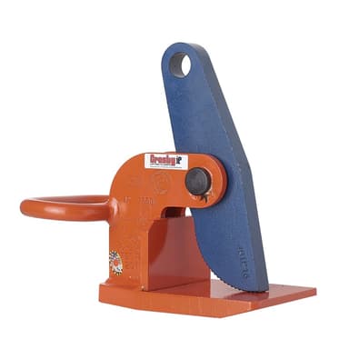
IPH10JE Horizontal Clamp — Large Jaw

IPH10JE Horizontal Clamp — Large Jaw

Basic horizontal clamp for thicker plate

3.0 – 12.0 t

per pair

For horizontal lifting and transfer

The IPH10E with a larger jaw opening, for plate too thick for the standard range.

Jaw / grip range
2.38 – 4.75 in
Surface hardness
363 HV10 (345 HB)
Minimum load
10% of the Working Load Limit

Best for

  • Thick plate handled horizontally
  • Heavy fabrication
  • Shipyard and structural work
Crosby’s product details
  • Available in capacities of 2.0 thru 25 metric tons.
  • Higher Working Load Limits available upon request.
  • Welded alloy steel body for strength and smaller size. Forged alloy, components where required.
  • Equipped with handle for easy placement.
  • Individually Proof Tested to 2 times the Working Load Limit with certification.
  • Company name (Crosby IP), logo, Working Load Limit and jaw opening permanently stamped on body.
  • Each product is individually serialized, with the serial number and Proof Load test date stamped on body. User manual with test certificate is included with each clamp.
  • Maintenance and repair spare kits are available.
  • Manufactured by an ISO 9001 facility.
5 models — sizes, jaw openings and stock numbers
ModelWLL (t, per pair)Jaw / grip range (in)Weight each (lb)Stock no.
IPH10JE32.38 - 4.75192703553
IPH10JE4.52.38 - 4.75262703554
IPH10JE62.38 - 4.75332703555
IPH10JE92.38 - 4.75452703556
IPH10JE122.38 - 4.75532703557
  • *Design Factor based on EN 13155 and ASME B30.20.
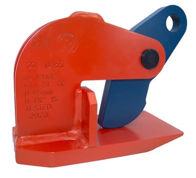
IPHOZ Horizontal Clamp for Sagging Plates

IPHOZ Horizontal Clamp for Sagging Plates

Built for plate that bends under its own weight

0.75 – 12.0 t

per pair

For Horizontal Lifting and Transfer

Thin or long plate sags when you pick it flat, and that bending peels a standard horizontal clamp off the edge. The IPHOZ is designed to hold on while the plate flexes.

Jaw / grip range
0 – 2.38 in
Surface hardness
363 HV10 (345 HB)
Minimum load
10% of the Working Load Limit

Best for

  • Long or thin plate that won't stay flat
  • Sheet handling where sag is unavoidable
  • Plate where a standard horizontal clamp lets go
Crosby’s product details
  • Available in a wide variety of capacities and jaw openings.
  • Higher Working Load Limits available upon request.
  • Welded alloy steel body for strength and smaller size. Forged alloy, components where required.
  • Equipped with handle for easy placement.
  • Individually Proof Tested to 2 times the Working Load Limit with certification.
  • Crosby IP logo, Working Load Limit and jaw opening permanently stamped on body.
  • Each product is individually serialized, with the serial number and Proof Load test date stamped on body. User manual with test certificate is included with each clamp.
  • Maintenance and repair kits are available.
  • Temperature range -40 °F (-40 °C) to +212 °F (+100 °C)
7 models — sizes, jaw openings and stock numbers
ModelWLL (t, per pair)Jaw / grip range (in)Weight each (lb)Stock no.
IPHOZ0.750 - 1.1962705401
IPHOZ1.50 - 1.75122705402
IPHOZ30 - 1.75172705403
IPHOZ4.50 - 1.75212705404
IPHOZ60 - 2.38342705405
IPHOZ90 - 2.38552705406
IPHOZ120 - 2.38642705407
  • *Design Factor based on EN 13155 and ASME B30.20.
9 series

Beam clamps

Grips a beam flange rather than plate

IPBC Beam Clamp with Pretension

IPBC Beam Clamp with Pretension

Clamps onto a beam flange, with pretension

1.0 – 3.0 t

per clamp

For Horizontal Transfer - with Pretension System.

A clamp for picking beams rather than plate, with a pretension system that holds it on the flange before the load comes up.

Jaw / grip range
0 – 1 in
Surface hardness
363 HV10 (345 HB)
Minimum load
10% of the Working Load Limit

Best for

  • Lifting and placing structural beams
  • Steel erection
  • Beam handling in a fabrication shop
Crosby’s product details
  • Available in a wide variety of capacities and jaw openings.
  • Higher Working Load Limits available upon request.
  • Welded alloy steel body for strength and smaller size. Forged alloy, components where required.
  • Equipped with handle for easy placement.
  • Individually Proof Tested to 2 times the Working Load Limit with certification.
  • Crosby IP logo, Working Load Limit and jaw opening permanently stamped on body.
  • Each product is individually serialized, with the serial number and Proof Load test date stamped on body. User manual with test certificate is included with each clamp.
  • Maintenance and repair kits are available.
  • Temperature range -40 °F (-40 °C) to +212 °F (+100 °C)
3 models — sizes, jaw openings and stock numbers
ModelWLL (t, each)Jaw / grip range (in)Weight each (lb)Stock no.
IPBC10 - 0.817.722700410
IPBC20 - 1.0014.32700411
IPBC30 - 1.0018.82700412
  • *Design Factor based on EN 13155 and ASME B30.20.
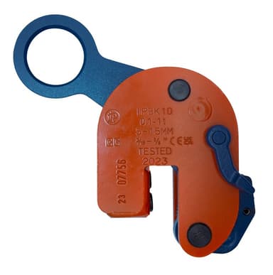
IPBK10 Beam Transfer Clamp

IPBK10 Beam Transfer Clamp

Transfer and stacking in the H position

0.5 – 4.0 t

per clamp

For the transfer and stacking of steel beams.

For transferring and stacking beams lying in the H position — where the web is horizontal and a standard beam clamp has nothing to grip.

Jaw / grip range
0.19 – 1.13 in
Surface hardness
363 HV10 (345 HB)
Minimum load
10% of the Working Load Limit

Best for

  • Stacking beams in a yard
  • Beam transfer in the H position
  • Structural steel handling
Crosby’s product details
  • Available in a wide variety of capacities and jaw openings.
  • Higher Working Load Limits available upon request.
  • Welded alloy steel body for strength and smaller size. Forged alloy components, where required.
  • Individually Proof Tested to 2 times the Working Load Limit with certification.
  • Crosby IP logo, Working Load Limit and jaw opening permanently stamped on body.
  • Each product is individually serialized, with the serial number and Proof Load test date stamped on body. User manual with test certificate is included with each clamp.
  • Minimum WLL of 10% of Maximum WLL.
  • For use with materials with a plate surface hardness to 279HV10, only 5% of minimum WLL is needed.
  • Maintenance and repair kits are available.
  • Temperature range -40 °F (-40 °C) to +212 °F (+100 °C)
4 models — sizes, jaw openings and stock numbers
ModelWLL (t, each)Jaw / grip range (in)Weight each (lb)Stock no.
IPBK100.50.19 - 0.635.292703931
IPBK1010.19 - 0.635.732703837
IPBK1020.19 - 1.0016.12703838
IPBK1040.19 - 1.1337.32703839
  • *Design Factor based on EN 13155 and ASME B30.20.
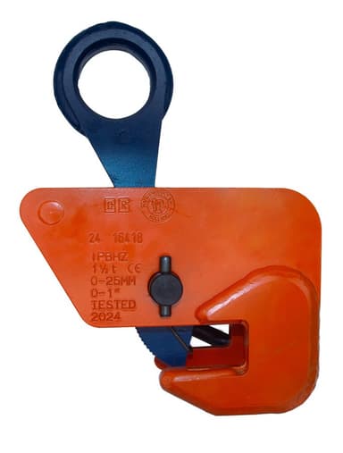
IPBHZ Beam Clamp

IPBHZ Beam Clamp

Lifting and transfer of steel beams, 0.75 through 12 ton

0.75 – 12.0 t

per clamp

For the lifting and transfer of steel beams.

A beam clamp sized by flange thickness for lifting and transferring structural steel. Welded alloy body, forged alloy components where required, proof tested with certificate.

Jaw / grip range
0 – 1.56 in

Best for

  • Lifting and transferring beams in a shop or yard
  • Steel erection
Crosby’s product details
  • Available in a wide variety of capacities and jaw openings.
  • Higher Working Load Limits available upon request.
  • Welded alloy steel body for strength and smaller size. Forged alloy components, where required.
  • Individually Proof Tested to 2 times the Working Load Limit with certification.
  • Crosby IP logo, Working Load Limit and jaw opening permanently stamped on body.
  • Each product is individually serialized, with the serial number and Proof Load test date stamped on body. User manual with test certificate is included with each clamp.
  • Maintenance and repair kits are available.
  • Temperature range -40 °F (-40 °C) to +212 °F (+100 °C)
5 models — sizes, jaw openings and stock numbers
ModelWLL (t, each)Jaw / grip range (in)Weight each (lb)Stock no.
IPBHZ0.750 - 1.006.612705461
IPBHZ1.50 - 1.0013.22705462
IPBHZ30 - 1.5623.22705463
IPBHZ4.50 - 1.5655.12705464
IPBHZ120 - 1.5693.32705467
  • *Design Factor based on EN 13155 and ASME B30.20.
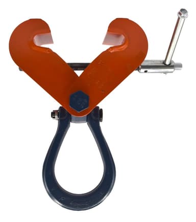
IPTK / IPTKW / IPTKU / IPTKUD Screw Beam Clamp

IPTK / IPTKW / IPTKU / IPTKUD Screw Beam Clamp

Screw-type beam clamp — a transfer clamp and a temporary tackle eye

2.0 – 25.0 t

per clamp

For transferring steel beams and attaching tackle eye.

Screws onto a beam flange for transferring the beam or for hanging tackle from it. Four versions differ in the eye: with hoisting eye, without, with a hinged eye, and with a double locking device. Sized by flange width.

Jaw / grip range
2.95 – 40.16 in

Best for

  • Transferring steel beams
  • A temporary attachment point on a beam for tackle
  • Rigging from existing structure without welding
  • IPTK — With hoisting eye
  • IPTKW — Without hoisting eye
  • IPTKU — With hinged hoisting eye
  • IPTKUD — With double locking device
Crosby’s product details
  • Available in a wide variety of capacities and jaw openings.
  • Higher Working Load Limits available upon request.
  • Welded alloy steel body for strength and smaller size. Forged alloy components, where required.
  • Individually Proof Tested to 2 times the Working Load Limit with certification.
  • Crosby IP logo, Working Load Limit and jaw opening permanently stamped on body.
  • Each product is individually serialized, with the serial number and Proof Load test date stamped on body. User manual with test certificate is included with each clamp.
  • Maintenance and repair kits are available.
  • Temperature range -40 °F (-40 °C) to +212 °F (+100 °C)
19 models — sizes, jaw openings and stock numbers
ModelWLL (t, each)Jaw / grip range (in)Weight each (lb)Stock no.
IPTK22.95 - 7.4813.22700996
IPTK32.95 - 7.4814.32700997
IPTK45.91 - 11.0218.72700998
IPTK54.72 - 13.7824.32700994
IPTK2517.72 - 40.164962702999
IPTKW23.00 - 7.508.822700966
IPTKW33.00 - 7.509.922700967
IPTKW45.88 - 11.2513.92700968
IPTKW54.75 - 13.7519.42700969
IPTKU23.00 - 7.5012.62707996
IPTKU33.00 - 7.5014.12707997
IPTKU44.75 - 11.2526.72707998
IPTKU54.75 - 13.75322707994
IPTKU107.88 - 18.0090.42707970
IPTKUD23.00 - 7.5013.22709996
IPTKUD33.00 - 7.5014.62709993
IPTKUD44.75 - 11.2527.12709995
IPTKUD54.75 - 13.7533.72709994
IPTKUD107.88 - 18.0094.82709970
  • * Design Factor based on EN 13155 and ASME B30.20.
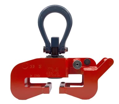
IPTKA Beam Clamp

IPTKA Beam Clamp

Hinged body, self-locking, bail swivels 360°

1.0 – 15.0 t

per clamp

A beam clamp with a hinged body that closes on the flange and locks itself, handgrips for placing it, and a hoisting eye that doubles as the tightening handle. The bail swivels through 360° and pivots 180°, so it takes a pull from any direction.

Jaw / grip range
2.8 – 16 in

Best for

  • Beam handling where the clamp is fitted and removed often
  • Tight spaces where a screw clamp can't be tightened
  • A wide range of profile sizes with one clamp
Crosby’s product details
  • Bail swivels 360° and pivots 180°.
  • Easy to close and open with a hinged body with self-locking device.
  • Easy to handle with handgrips.
  • No interference or space limitations when tightening the clamp.
  • Multi-purpose hoisting eye to be used for tightening as well as for hoisting.
  • Maintenance and repair kits are available.
  • Can be used for a wide range of profile sizes.
  • Individually Proof Tested to 2 times the Working Load Limit with certification.
  • Crosby IP logo, Working Load Limit and jaw opening permanently stamped on body.
  • Temperature range -40 °F (-40 °C) to +212 °F (+100 °C)
9 models — sizes, jaw openings and stock numbers
ModelWLL (t, each)Jaw / grip range (in)Weight each (lb)Stock no.
IPTKA13.5 - 7.013.52707101
IPTKA33.9 - 8.1352707111
IPTKAJ132.8 - 4.931.32707116
IPTKAJ233.9 - 8.135.32707117
IPTKA53.9 - 1251.42707065
IPTKAJ152.8 - 4.937.32707114
IPTKAJ255.1 - 1251.22707115
IPTKA105.5 - 161372707118
IPTKA155.5 - 161572707124
  • *Design Factor based on EN 13155 and ASME B30.20.
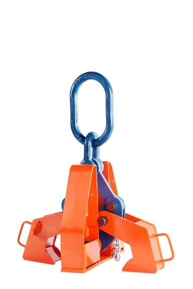
IPBCNS Beam Clamp

IPBCNS Beam Clamp

Three-point grip, 13.5 through 32 ton — the heavier the beam, the harder it holds

13.5 – 32.0 t

per clamp

NOTE: Control the beam at all times. Beams should be gripped as near the center as possible. Snubbing lines at each end must be used to control excessive twisting or swinging, and to guide the beam to its proper place. Each lifting situation may have a specific demand which should be addressed before lifting.

A high-capacity beam clamp that grips at three points. Set it on the load and the tongs open and slide under the flange on their own; the center plate and tongs work together so clamping pressure rises with the weight of the beam. Sized by flange grip range and thickness.

Jaw / grip range
7 – 36 in

Best for

  • Heavy structural beams without slings, chokers or spreader bars
  • Beams with studs welded to the surface — the base is recessed for them
  • Steel erection and heavy fabrication
Crosby’s product details
  • When lifting, these beam clamps grip the beam at three points, and when properly balanced and safely guided, the beam can be handled even if the clamp is slightly off center lengthwise.
  • Capacities: 13.5 through 32 metric tons (higher Working Load Limits are available upon request).
  • Eliminates the need for slings, chokers, and spreader bars.
  • When applied to load, the tongs automatically open and slide under the flange of the beam.
  • Center plate and gripping tongs work together - the heavier the beam, the greater the clamping pressure.
  • Base is recessed to accept studs welded to the beam surface.
  • Welded alloy steel body for strength and smaller size. Forged alloy components, where required.
  • Individually Proof Tested to 2 times the Working Load Limit with certification.
  • Crosby IP logo, Working Load Limit and jaw opening permanently stamped on body.
  • Each product is individually serialized, with the serial number and Proof Load test date stamped on body. User manual with test certificate is included with each clamp.
  • Maintenance and repair kits are available.
  • Temperature range -40 °F (-40 °C) to +212 °F (+100 °C)
3 models — sizes, jaw openings and stock numbers
ModelWLL (t, each)Jaw / grip range (in)Weight each (lb)Stock no.
IPBCNS13.57 - 171372702018
IPBCNS22.516 - 242912702036
IPBCNS3216 - 365292702054
  • *Design factor based on EN 13155 and ASME B30.20.
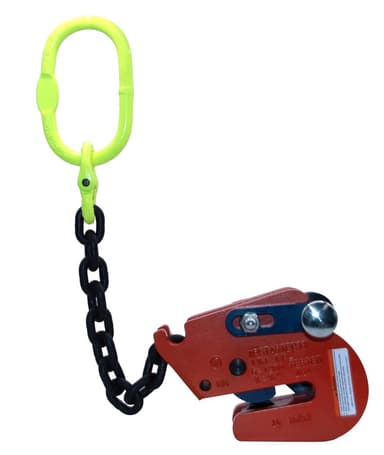
IPSTARTEC11 Beam Clamp

IPSTARTEC11 Beam Clamp

Lifting, transferring and controlled tilting of steel beams

1.5 – 2.5 t

per clamp

For Lifting, Transferring and Controlled Tilting of Steel Beams.

A beam clamp for lifts where the beam has to be tilted under control as well as moved. Handle for placement; sized by flange thickness.

Jaw / grip range
0.25 – 0.75 in

Best for

  • Setting beams that must be tilted into position
  • Beam transfer in a fabrication shop
Crosby’s product details
  • Available in a wide variety of capacities and jaw openings.
  • Higher Working Load Limits available upon request.
  • Welded alloy steel body for strength and smaller size. Forged alloy, components where required.
  • Equipped with handle for easy placement.
  • Individually Proof Tested to 2 times the Working Load Limit with certification.
  • Crosby IP logo, Working Load Limit and jaw opening permanently stamped on body.
  • Each product is individually serialized, with the serial number and Proof Load test date stamped on body. User manual with test certificate is included with each clamp.
  • Maintenance replacement parts are available.
  • Temperature range -40 °F (-40 °C) to +212 °F (+100 °C)
2 models — sizes, jaw openings and stock numbers
ModelWLL (t, each)Jaw / grip range (in)Weight each (lb)Stock no.
IPSTARTEC111.50.25 - 0.5014.62701812
IPSTARTEC112.50.25 - 0.75322701822
  • *Design Factor based on EN 13155 and ASME B30.20.
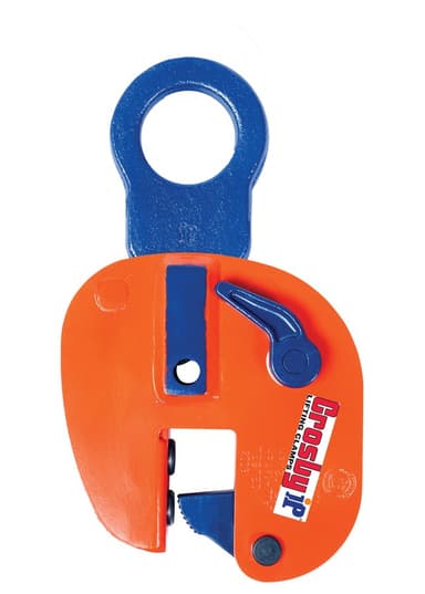
IPBUUZ / IPBUZ Bulb Profile Clamp

IPBUUZ / IPBUZ Bulb Profile Clamp

Lifting, transferring and placing bulb profiles onto a hull, perpendicular

0.75 – 3.75 t

per clamp

For Lifting, Transferring and Placing Bulb Profiles onto Ship’s Hulls Perpendicularly.

For handling Holland bulb (HP) profiles in shipbuilding — lifting them, moving them, and placing them onto the hull perpendicularly. The IPBUUZ has a universal hoisting eye; the IPBUZ a fixed one. Sized by HP profile.

Jaw / grip range
HP 4.75 – 17 in
Minimum load
10% of the maximum Working Load Limit

Best for

  • Shipyard profile handling
  • Placing stiffeners perpendicular to a hull
  • IPBUUZ — Universal hoisting eye
  • IPBUZ — Fixed hoisting eye
Crosby’s product details
  • Available in a wide variety of capacities and jaw openings.
  • Higher Working Load Limits available upon request.
  • Welded alloy steel body for strength and smaller size. Forged alloy components, where required.
  • Individually Proof Tested to 2 times the Working Load Limit with certification.
  • Crosby IP logo, Working Load Limit and jaw opening permanently stamped on body.
  • Each product is individually serialized, with the serial number and Proof Load test date stamped on body. User manual with test certificate is included with each clamp.
  • Minimum WLL of 10% of maximum WLL.
  • Maintenance and repair kits are available.
  • Temperature range -40 °F (-40 °C) to +212 °F (+100 °C)
4 models — sizes, jaw openings and stock numbers
ModelWLL (t, each)Jaw / grip range (in)Weight each (lb)Stock no.
IPBUUZ0.75HP 4.75 - 7.8816.32705601
IPBUZ0.75HP 4.75 - 7.8813.72705600
IPBUZ1.5HP 8.63 - 17.0033.12705701
IPBUZ3.75HP 8.63 - 17.0064.42705702
  • *Design Factor based on EN 13155 and ASME B30.20.
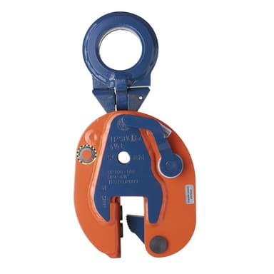
  • †Profile A is the type of Holland Bulb (HP) style and size material.
IPSBUUZ / IPSBUSUZ Ship Section Clamp

IPSBUUZ / IPSBUSUZ Ship Section Clamp

Lifting, transferring and placing complete ship sections, 4.5 through 9 ton

4.5 – 9.0 t

per clamp

For Lifting, Transferring and Placing Complete Shipsections.

Clamps onto the bulb-profile stiffeners of a complete ship section so the section itself can be lifted and placed. HP 4 in through HP 17 in profiles; universal hoisting eye.

Jaw / grip range
HP 4 – 17 in
Minimum load
10% of the maximum Working Load Limit

Best for

  • Moving complete ship sections
  • Shipyard block assembly
Crosby’s product details
  • Available in capacities of 4.5 through 9 metric tons (higher Working Load Limits are available upon request).
  • Wide variety of jaw openings available: HP 4" to HP 17".
  • Welded alloy steel body for strength and smaller size. Forged alloy components, where required.
  • Individually Proof Tested to 2 times the Working Load Limit with certification.
  • Crosby IP logo, Working Load Limit and jaw opening permanently stamped on body.
  • Each product is individually serialized, with the serial number and Proof Load test date stamped on body. User manual with test certificate is included with each clamp.
  • Minimum WLL of 10% of maximum WLL.
  • Maintenance and repair kits are available.
  • Temperature range -40 °F (-40 °C) to +212 °F (+100 °C)
4 models — sizes, jaw openings and stock numbers
ModelWLL (t, each)Jaw / grip range (in)Weight each (lb)Stock no.
IPSBUUZ4.5HP 4.00 - 6.2534.22705771
IPSBUUZ9HP 4.00 - 6.2594.82705773
IPSBUSUZ4.5HP 7.13 - 17.0083.82705772
IPSBUSUZ9HP 7.13 - 17.001522705774
  • *Design Factor based on EN 13155 and ASME B30.20.
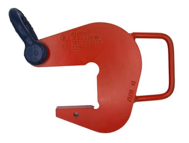
  • † Profile A is the type of Holland Bulb (HP) style and size material.

1 series

Pipe clamps

Cradles pipe and tube without a sling

IPPH Pipe Hook

IPPH Pipe Hook

Lifts pipe and tube without a sling round it

2.0 – 20.0 t

per pair

For lifting pipe, tube, or any similarly shaped fabrications.

Hooks that cradle pipe for lifting, used in pairs. Nylon inserts protect coated pipe and are sized to the pipe diameter.

Surface hardness
Suits carbon and coated pipe
Minimum load
10% of the Working Load Limit

Best for

  • Pipe and tube handling in a yard or on site
  • Coated pipe that a sling would damage
  • Repetitive pipe picks
Crosby’s product details
  • Crosby IP Pipe Hooks provide a fast and efficient method for lifting pipe, tube or any similarly shaped fabrications.
  • Alloy steel plate construction.
  • Equipped with a convenient handle.
  • Equipped with a Bolt Type Shackle.
  • Optional non marring inserts available.
  • Used in pairs with 45° - 60° horizontal angle or 60° - 90° included angle.
  • Temperature range -40 °F (-40 °C) to +212 °F (+100 °C)
6 models — sizes, jaw openings and stock numbers
ModelWLL (t, per pair)Jaw / grip range (in)Weight each (lb)Stock no.
IPPH22.0662734500
IPPH42.819.92734509
IPPH64.06172734518
IPPH106.0638.12734527
IPPH156.0648.12734536
IPPH206.0650.92734545
  • *Design factor based on EN13155 and ASME B30.20.
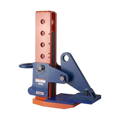
  • **NOTE: To determine grip opening when equipped with an insert, add the insert thickness shown in the Pipe Hook Insert table below.

7 series

Specialty clamps

Bundles, lifting eyes, and one-off jobs

IPPE10 Bundle Lifting Clamp

IPPE10 Bundle Lifting Clamp

Lifts a stack of plates, not just the top one

3.0 – 12.0 t

per clamp

For lifting and transporting non-bendable sheet metal in a horizontal position.

For picking up bundles of plate together rather than one at a time. Available non-marring for finished material.

Jaw / grip range
0 – 16.5 in
Surface hardness
363 HV10 (345 HB)
Minimum load
10% of the Working Load Limit

Best for

  • Moving plate in bundles off a truck or rack
  • Reducing pick count in a plate yard
  • Bundled sheet and plate stock
  • IPPE10B / D / H — Standard, by bundle thickness range
  • IPPE10BNM / DNM / HNM — Non-marring versions
Crosby’s product details
  • Available in a wide variety of capacities and jaw openings.
  • Higher Working Load Limits available upon request.
  • Welded alloy steel body for strength and smaller size. Forged alloy components, where required.
  • Individually Proof Tested to 2 times the Working Load Limit with certification.
  • Crosby IP logo, Working Load Limit and jaw opening permanently stamped on body.
  • Each product is individually serialized, with the serial number and Proof Load test date stamped on body. User manual with test certificate is included with each clamp.
  • Maintenance and repair kits are available.
  • IPPE10: Magnets in foot plate (also applies for D and H Type).
  • IPPE10NM: Non-marring (also applies for D and H-Type).
  • IPPE10: Temperature range -40 °F (-40 °C) to +212 °F (+100 °C)
  • IPPE10NM: Temperature range -4 °F (-20 °C) to +158 °F (+70 °C)
16 models — sizes, jaw openings and stock numbers
ModelWLL (t, each)Jaw / grip range (in)Weight each (lb)Stock no.
IPPE10B30 - 7.13252703862
IPPE10B60 - 7.13352703871
IPPE10B90 - 7.13542703888
IPPE10B120 - 7.13722703921
IPPE10D30 - 11.828.442703882
IPPE10H60 - 16.542.772703875
IPPE10H90 - 16.565.72703890
IPPE10H120 - 16.585.762703923
IPPE10BNM30 - 7.13272703864
IPPE10BNM60 - 7.13382703872
IPPE10BNM90 - 7.13612703894
IPPE10BNM120 - 7.13772703927
IPPE10DNM30 - 11.830.642703886
IPPE10HNM60 - 16.545.422703879
IPPE10HNM90 - 16.572.532703920
IPPE10HNM120 - 16.591.492703929
  • *Design Factor based on EN 13155 and ASME B30.20.
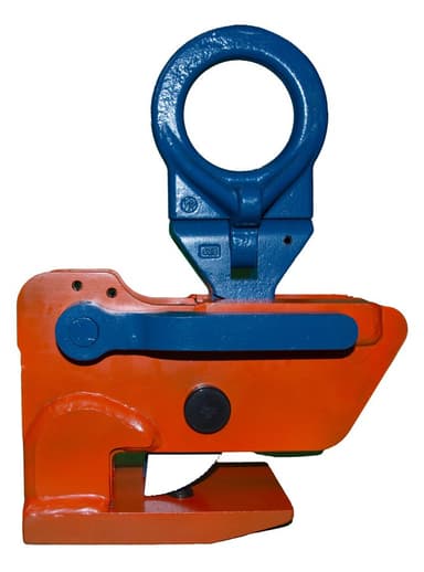
IPHGZ / IPHGUZ Lifting Eye

IPHGZ / IPHGUZ Lifting Eye

A temporary rated lifting point that clamps on

0.75 – 4.5 t

per clamp

For Horizontal Transfer - with Pretension System

Creates an attachment point on plate or structure without welding a lug. The IPHGUZ swivels for pull in any direction; the IPHGZ is fixed. Both have a locking device.

Jaw / grip range
0 – 1.56 in
Surface hardness
363 HV10 (345 HB)
Minimum load
10% of the Working Load Limit

Best for

  • Temporary lifting points without welding
  • Turning and uprighting fabrications
  • Awkward one-off picks
  • IPHGUZ — Universal lifting eye — swivels
  • IPHGZ — Fixed hoisting eye
Crosby’s product details
  • Available in a wide variety of capacities and jaw openings.
  • Higher Working Load Limits available upon request.
  • Welded alloy steel body for strength and smaller size. Forged alloy, components where required.
  • Equipped with handle for easy placement.
  • Individually Proof Tested to 2 times the Working Load Limit with certification.
  • Company name (CrosbyIP), logo, Working Load Limit and jaw opening permanently stamped on body.
  • Each product is individually serialized, with the serial number and Proof Load test date stamped on body. User manual with test certificate is included with each clamp.
  • Maintenance and repair kits are available.
  • Manufactured by an ISO 9001 facility.
  • Temperature range -40 °F (-40 °C) to +212 °F (+100 °C)
7 models — sizes, jaw openings and stock numbers
ModelWLL (t, each)Jaw / grip range (in)Weight each (lb)Stock no.
IPHGUZ1.50 - 1.0019.82705455
IPHGUZ30 - 1.5643.92705456
IPHGUZ4.50 - 1.5666.12705457
IPHGZ0.750 - 1.008.822705451
IPHGZ1.50 - 1.004.412705452
IPHGZ30 - 1.5627.12705453
IPHGZ4.50 - 1.5655.12705454
  • *Design Factor based on EN 13155 and ASME B30.20.
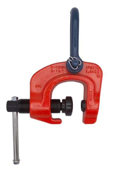
IPSC10 Screw Clamp — positioning only

IPSC10 Screw Clamp — positioning only

For positioning and turning plate. Not a lifting clamp.

1.5 – 3.0 t

per clamp

Suitable for use in positioning & turning steel plates and sections. Not to be used as a lifting clamp.

A screw clamp for positioning and turning steel plate and sections during fit-up. Crosby is explicit that it is not to be used as a lifting clamp, and so are we: it holds and turns, it does not lift. Forged alloy body.

Jaw / grip range
0 – 2.38 in
Surface hardness
Steel to 30 Rc surface hardness

Best for

  • Positioning plate and sections for fit-up and welding
  • Turning work on the bench
Crosby’s product details
  • Available in a wide variety of capacities and jaw openings.
  • Higher Working Load Limits available upon request.
  • Suitable for steel with a surface hardness up to 30 Rc.
  • Forged alloy steel body for strength and smaller size. Forged alloy components, where required.
  • Individually Proof Tested to 2 times the Working Load Limit with certification.
  • Crosby IP logo, Working Load Limit and jaw opening permanently stamped on body.
  • Each product is individually serialized, with the serial number and Proof Load test date stamped on body. User manual with test certificate is included with each clamp.
  • Manufactured by an ISO 9001 facility.
  • Temperature range -40 °F (-40 °C) to +212 °F (+100 °C)
2 models — sizes, jaw openings and stock numbers
ModelWLL (t, each)Jaw / grip range (in)Weight each (lb)Stock no.
IPSC101.50 - 1.5710.12703857
IPSC1030 - 2.3818.52703858
  • *Design Factor based on EN 13155 and ASME B30.20.
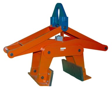
IPBG Barrier Grab

IPBG Barrier Grab

Hands-free handling of road barriers

4.0 – 4.0 t

per clamp

The CrosbyIP Barrier Grab provides a fast and efficient method for handling road barriers.

A grab for concrete road barriers: set it on the barrier, lift, and it closes on its own — no one has to touch the load. Polyurethane pads protect the barrier and are replaceable.

Jaw / grip range
6 – 12 in

Best for

  • Placing and picking up highway barrier sections
  • Road and bridge contractors
Crosby’s product details
  • Hands-free operation.
  • Welded alloy steel construction for strength and smaller size.
  • Comes equipped with polyurethane pads. (Replacement kits are available.)
  • Individually Proof Tested to 2 times the Working Load Limit with certification.
  • Crosby IP logo, Working Load Limit and jaw opening permanently stamped on body.
  • Each product is individually serialized, with the serial number and Proof Load test date stamped on body. User manual with test certificate is included with each clamp.
  • Temperature range -4 °F (-20 °C) to +158 °F (+70 °C)
1 models — sizes, jaw openings and stock numbers
ModelWLL (t, each)Jaw / grip range (in)Weight each (lb)Stock no.
IPBG46 - 123452704018
  • *Design factor based on EN13155 and ASME B30.20.
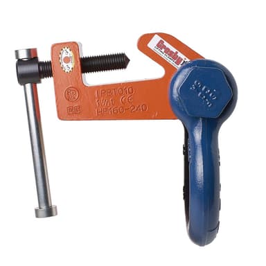
IPBTO10 Temporary Tackle Eye for Bulb Profiles

IPBTO10 Temporary Tackle Eye for Bulb Profiles

A rated lifting point that clamps onto HP bulb-profile stiffeners

1.5 – 6.0 t

per clamp

For use as a temporary tackle eye in spaces that have been reinforced with HP (bulb) profiles such as engine rooms and shipsections.

Clamps onto a Holland bulb (HP) profile to give you a temporary tackle eye in spaces stiffened with them — engine rooms and ship sections. Sized by the HP profile it fits.

Jaw / grip range
HP 6.5 – 17 in

Best for

  • Rigging inside ship sections and engine rooms
  • Temporary lifting points on bulb-profile stiffeners
Crosby’s product details
  • Available in a wide variety of capacities and jaw openings.
  • Higher Working Load Limits available upon request.
  • Alloy steel body for strength and smaller size. Forged alloy components, where required.
  • Individually Proof Tested to 2 times the Working Load Limit with certification.
  • Crosby IP logo, Working Load Limit and jaw opening permanently stamped on body.
  • Each product is individually serialized, with the serial number and Proof Load test date stamped on body. User manual with test certificate is included with each clamp.
  • Maintenance and repair kits are available.
  • Temperature range -40 °F (-40 °C) to +212 °F (+100 °C)
3 models — sizes, jaw openings and stock numbers
ModelWLL (t, each)Jaw / grip range (in)Weight each (lb)Stock no.
IPBTO101.5HP 6.5 - 9.44112700980
IPBTO103HP 9.44 - 12.56132700986
IPBTO106HP 11.75 - 17.0028.72700991
  • *Design Factor based on EN 13155 and ASME B30.20.
  • †Profile A is the type of Holland Bulb (HP) style and size material.
IPDV Drum Clamp

IPDV Drum Clamp

Lifts, moves and transfers 50–55 gallon steel-top drums

0.5 – 0.5 t

per clamp

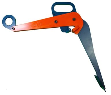
Designed to lift, move and transfer 50-55 gallon drums with steel tops.

A clamp for drums rather than plate. It takes a 50 to 55 gallon drum with a steel top from above, so the drum moves by crane or hoist instead of being tipped and rolled.

Best for

  • Moving drums by hoist in a plant
  • Loading and unloading drums where a forklift can't reach
Crosby’s product details
  • Available in a wide variety of capacities and jaw openings.
  • Higher Working Load Limits available upon request.
  • Welded alloy steel body for strength and smaller size. Forged alloy components, where required.
  • Individually Proof Tested to 2 times the Working Load Limit with certification.
  • Crosby IP logo, Working Load Limit and jaw opening permanently stamped on body.
  • Each product is individually serialized, with the serial number and Proof Load test date stamped on body. User manual with test certificate is included with each clamp
  • Maintenance and repair kits are available.
  • Temperature range -40 °F (-40 °C) to +212 °F (+100 °C)
1 models — sizes, jaw openings and stock numbers
ModelWLL (t, each)Jaw / grip range (in)Weight each (lb)Stock no.
IPDV0.5—15.72700118
  • *Design Factor based on EN 13155 and ASME B30.20.
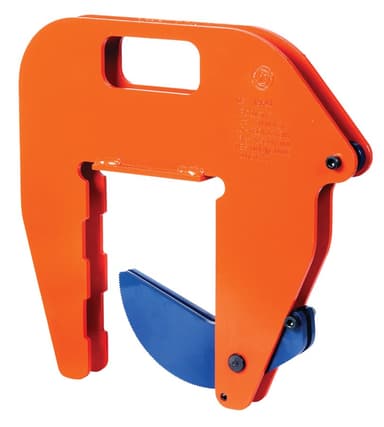
IPCC Concrete Pipe Clamp

IPCC Concrete Pipe Clamp

Lifting and transferring concrete pipe sections and wells — used in pairs

1.0 – 1.0 t

per pair

For Lifting and Transferring Concrete Pipe Sections and Wells.

Grips the wall of a concrete pipe section or well ring so it can be lifted and set without a sling round it. Rated per pair. Handle for placement.

Jaw / grip range
1.56 – 5.5 in

Best for

  • Setting concrete pipe and manhole sections
  • Precast yards and utility contractors
Crosby’s product details
  • Available in a wide variety of capacities and jaw openings.
  • Higher Working Load Limits available upon request.
  • Welded alloy steel body for strength and smaller size. Forged alloy, components where required.
  • Equipped with handle for easy placement.
  • Individually Proof Tested to 2 times the Working Load Limit with certification.
  • Crosby IP logo, Working Load Limit and jaw opening permanently stamped on body.
  • Each product is individually serialized, with the serial number and Proof Load test date stamped on body. User manual with test certificate is included with each clamp.
  • Maintenance replacement parts are available.
  • Temperature range -40 °F (-40 °C) to +212 °F (+100 °C)
1 models — sizes, jaw openings and stock numbers
ModelWLL (t, per pair)Jaw / grip range (in)Weight each (lb)Stock no.
IPCC11.56 - 5.5020.32700037
  • *Design Factor based on EN 13155 and ASME B30.20.

Accessory

Pipe hook inserts

Nylon inserts for the IPPH pipe hook, sized to the pipe. Not rated lifting devices in their own right — the hook carries the rating.

ModelPipe diameter (in)Weight (lb)Stock no.
IPPHI3 – 121.612734900
IPPHI12 – 181.732734909
IPPHI18 – 302.482734918
IPPHI30 – 423.742734927
IPPHI42 – 525.712734936

Certification

Every clamp ships tested and serialized

  • Proof tested to 2× WLL. Individually, not by batch, and the certificate comes with the clamp.
  • Serialized. Serial number and proof load test date stamped on the body, so the paperwork can be matched to the clamp years later.
  • Marked. Working load limit and jaw opening stamped permanently — not on a tag that falls off.
  • Design factor to EN 13155 and ASME B30.20.
  • 10 year guarantee on standard Crosby IP clamps.

Keeping them in service

Clamps wear out, and it's the part you can't see

The cam and pivot do the gripping, and they wear. A clamp that looks fine can be well past the point where it holds reliably — which is why OSHA wants them inspected and why Crosby sells maintenance kits rather than just replacements.

We inspect clamps, fit maintenance kits, and give you the records. Stock numbers for the kits are in the tables above.

Rigging inspection & repair →

Tell us the plate, we'll pick the clamp

Thickness, weight, material, surface finish, and whether it's lifted vertically or carried flat. Those five answers pick the clamp — and we'll tell you if you need them in pairs.